
Wire Tagger-101 by GPIO number.
Pick the same ESP32 board you selected on the flasher page. The map gives you the GPIO for each Tagger-101 signal and the short notes needed to avoid the easy wiring mistakes.
Wire After Flashing
Flash the bare board first. After it boots, disconnect USB power before adding wiring. Keep every module on 3.3 V logic, use one shared ground, and never drive an IR LED strip or motor directly from a GPIO pin.
Tagger-101
Tagger build with IR transmitter, hit receiver, trigger, reload, feedback, and OLED screen.
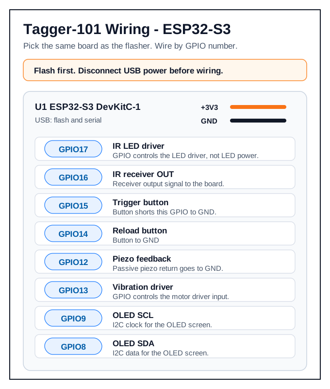
ESP32-S3 is an untested board schematic. It matches the firmware pin map, but we would love to hear how it behaves on real hardware.
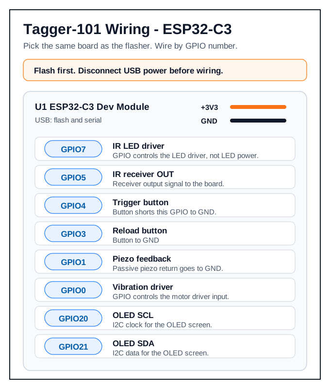
ESP32-C3 pins
GPIO numbers match the firmware pin profile for this board family.
| Part | GPIO | Beginner note |
|---|---|---|
| IR LED driver | GPIO7 | Driver input; LED current must come through a separate driver circuit. |
| IR receiver OUT | GPIO5 | Receiver output pin. |
| Trigger button | GPIO4 | Button connects GPIO to GND. |
| Reload button | GPIO3 | Button connects GPIO to GND. |
| Piezo | GPIO1 | Piezo to GND. |
| Vibration motor | GPIO0 | Driver input. |
| OLED SCL / SDA | GPIO20 / GPIO21 | OLED I2C pair. |
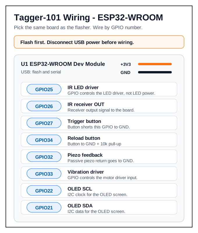
ESP32-WROOM module pins
GPIO numbers match the firmware pin profile for this board family.
| Part | GPIO | Beginner note |
|---|---|---|
| IR LED driver | GPIO25 | Driver input; LED current must come through a separate driver circuit. |
| IR receiver OUT | GPIO26 | Receiver output pin. |
| Trigger button | GPIO27 | Button connects GPIO to GND. |
| Reload button | GPIO34 | Add 10 kOhm pull-up to 3V3; button pulls to GND. |
| Piezo | GPIO32 | Piezo to GND. |
| Vibration motor | GPIO33 | Driver input. |
| OLED SCL / SDA | GPIO22 / GPIO21 | OLED I2C pair. |
ESP32-S3 pins (untested)
GPIO numbers match the firmware pin profile for this board family.
| Part | GPIO | Beginner note |
|---|---|---|
| IR LED driver | GPIO17 | Driver input; LED current must come through a separate driver circuit. |
| IR receiver OUT | GPIO16 | Receiver output pin. |
| Trigger button | GPIO15 | Button connects GPIO to GND. |
| Reload button | GPIO14 | Button connects GPIO to GND. |
| Piezo | GPIO12 | Piezo to GND. |
| Vibration motor | GPIO13 | Driver input. |
| OLED SCL / SDA | GPIO9 / GPIO8 | OLED I2C pair. |